Software for measuring machines and measuring arms
The right software plays an important role in modern metrology. Whether measurements are performed using a measuring machine or a portable measuring arm, software is used to control the measurement process, collect data, and generate clear reports. The right software makes it easier to work efficiently and contributes to improved accuracy and repeatability in the measurement process.
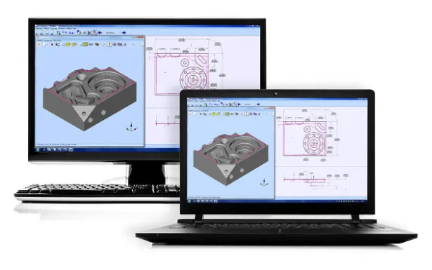
In many operations, CAD based software is used for both manual measurements and automated measurement programs. This allows measurements to be performed directly at the machine or prepared offline on a workstation.
Software for measuring machines and measuring arms in practice
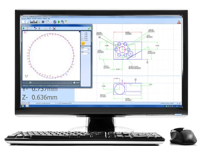
Software is used to prepare measurements, capture measurement points, and analyze results. As the component is measured in a measuring machine, a digital representation of the part is built within the software.
In many systems, a measurement program is also created automatically when a component is measured for the first time. These programs can then be reused when the next component is inspected, making the process faster and more efficient. Results can be presented in graphical reports or in table format, where nominal values, tolerances, and deviations are clearly displayed.
CAD based programming for measurement
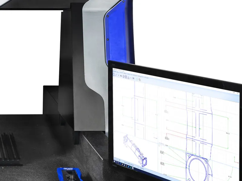
Measurement programs are created based on a CAD model of the component. With CAD programming functionality, the operator can click directly on the model’s surfaces to define where measurement points should be taken. The software then automatically interprets the type of geometry being measured, such as planes, lines, or circles.
In Aberlink 3D, a feature called Feature Predict is used. When the operator selects points on the model, Feature Predict analyzes the intended geometric feature, such as planes, lines, or circles, and automatically creates the correct measurement function. This speeds up programming and reduces the need for manual configuration.
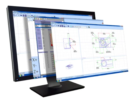
CAD based programming can be performed both directly on the measuring machine and offline on a separate workstation. This makes it possible to prepare measurement programs without interrupting production.
CAD comparison for complex geometries
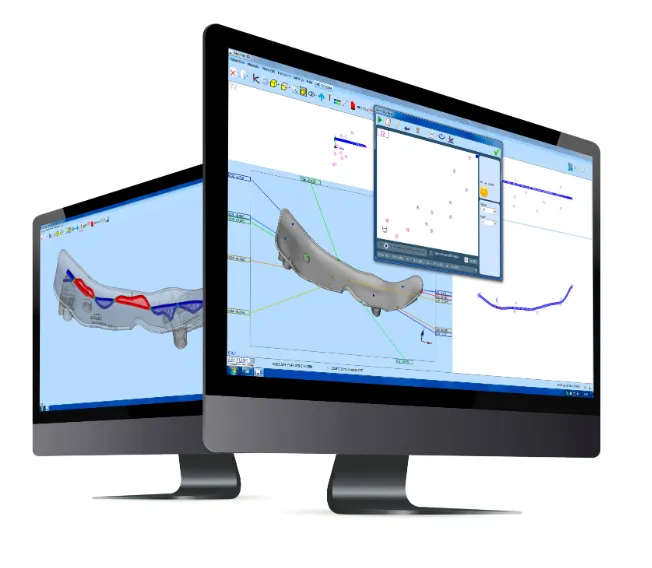
For complex geometries such as freeform surfaces, CAD comparison can be used to analyze results. In these cases, measured points are directly compared with the CAD model to show how well the component matches the design.
In Aberlink 3D, measurement points are aligned to the model according to the defined alignment. Deviations are then displayed as color coded areas on the model based on the measurement data, making it easy to identify where a component is within or outside tolerance.
Reports can be exported to formats such as Excel and can include graphical results or tables with dimensions, tolerances, and deviations.
Software as support for quality control
By combining measuring equipment such as measuring arms or measuring machines with the right software, it becomes easier to work systematically with quality control. The operator can follow the same workflow each time a component is measured, reducing operator influence and making results more comparable over time.
When programs and reports are clearly structured, it also becomes easier to identify deviations early and to document results for follow up and traceability.
Do you need help choosing the right software?
The choice of software affects how efficiently measurements can be performed. Requirements vary depending on the equipment, the complexity of the components, and how measurement is integrated into production.
Which software fits your measurement needs? Contact us at NYLI and we will help you find the right solution.